
In the hierarchy of off-grid survival, communication is no longer a luxury—it is critical infrastructure. Whether for emergency coordination, remote work, or real-time weather monitoring, satellite internet systems like Starlink have become the standard for “grid-down” connectivity. However, at Home Power Lab, our real-world 2026 benchmarking reveals a massive efficiency gap in how these systems are typically powered.
Quick Verdict: Starlink performs best when you eliminate needless AC conversion.
If your Starlink setup is being powered through a battery → inverter → power brick chain, you are paying an “inverter tax” every hour the system stays online. For off-grid and emergency communications, a direct DC path usually means better battery endurance, lower idle waste, and fewer voltage-related headaches.
Most users rely on the “Plug-and-Play” method: plugging the Starlink factory router into a portable power station’s AC outlet. While convenient, this approach is mathematically flawed for long-term survival. We call this the Inverter Tax, and in an off-grid scenario, it is the single biggest drain on your energy reserves.
Want to Learn More About Bypassing the Inverter Tax? Start Here
Before using third-party PoE injectors, DC-DC converters, or custom cabling, confirm your exact Starlink hardware generation and connector requirements. A wrong assumption on voltage, polarity, or pinout can damage equipment.
- Do not assume all Starlink dishes share the same power path or connector behavior.
- Gen 2 actuated systems are especially sensitive because proprietary cable and pinout assumptions can create failure points.
- Use only tested components from reputable vendors when building a custom DC chain.
- If you are not fully confident in your wiring path, stick with a known-safe adapter solution instead of improvising.
Pick the right Starlink DC path for your hardware
The correct solution depends less on “Starlink” in general and more on your specific dish generation, how much modification you are willing to do, and whether you want a reversible setup or a full custom power path.
Mini users
The Mini’s native DC-friendly design makes it the cleanest fit for portable and battery-first use. This is the easiest model to align with the article’s overall efficiency argument.
Gen 2 / actuated users
This is where caution matters most. Proprietary wiring behavior means users should rely on tested adapter paths and verified pinout knowledge instead of generic PoE assumptions.
Gen 3 / standard users
Often easier to integrate into cleaner DC strategies than older proprietary setups, but still worth validating against real voltage, connector, and power-delivery requirements before buying parts.
The Anatomy of the Inverter Tax: Double Conversion Loss
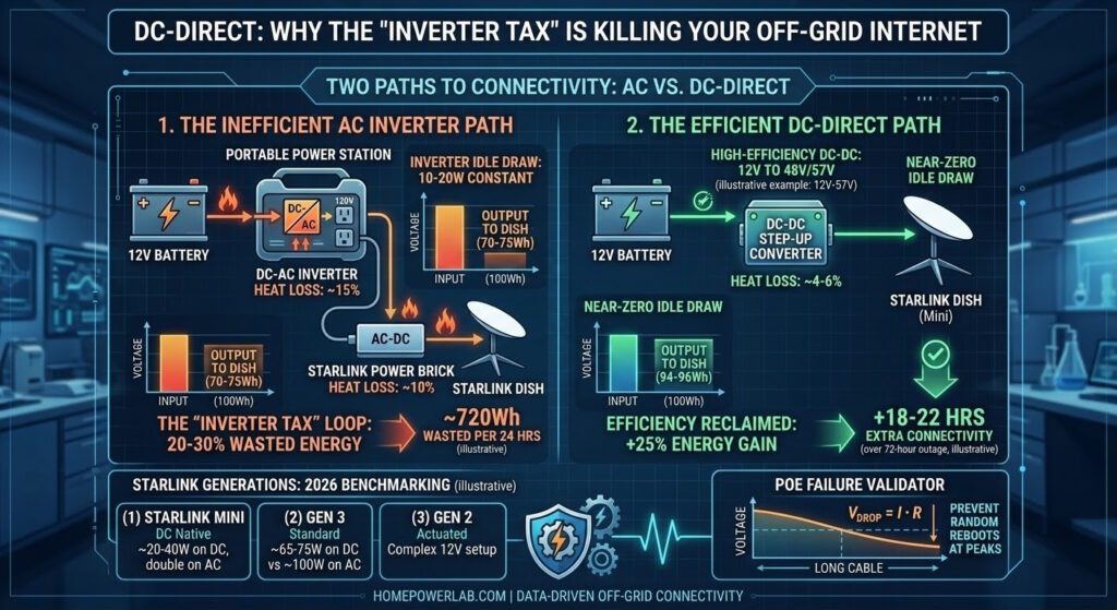
To understand why your battery dies 25–30% faster than expected, you have to follow the path of the electrons. Your portable power station stores energy as Direct Current (DC). Starlink hardware—including the dish and the internal router—also operates internally on Direct Current (DC).
When you use the standard AC factory setup, you are forcing the energy through a “conversion loop” that creates heat instead of connectivity:
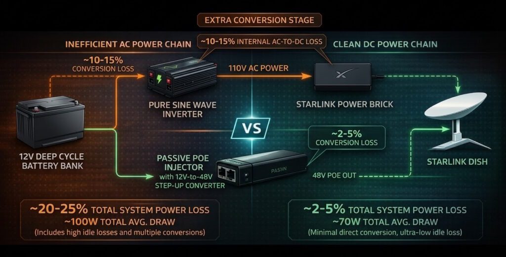
- DC to AC: Your power station’s inverter converts 12V or 24V battery power into 120V AC. This stage typically loses 10–15% of energy as heat.
- AC to DC: The Starlink power brick converts 120V AC back to DC (ranging from 30V to 57V, depending on the model). This stage loses another 7–10%.
When you factor in the Inverter Idle Draw—the constant 10W to 20W “cost” of just keeping the inverter’s cooling fans and internal circuits energized—you are paying a massive “Tax.” In our Lab tests, running a Starlink Gen 3 via a standard AC inverter consumes nearly 100 Watts, whereas a DC-Direct setup pulls closer to 70 Watts. That 30-Watt difference represents an extra 720 Watt-hours of energy wasted every 24 hours.
The efficiency argument only matters when readers understand the test assumptions. This article evaluates Starlink as a continuous communications load, where every watt of overhead compounds over time.
| Use profile | Always-on or long-duration operation rather than short, casual sessions |
|---|---|
| Battery context | Finite off-grid storage where parasitic loss has a direct runtime penalty |
| Comparison | Battery → inverter → Starlink power chain versus battery → DC-DC path |
| Main variables | Inverter idle draw, conversion efficiency, cable resistance, voltage drop, connector quality, and Starlink hardware generation |
| Reader takeaway | Convenience power paths may work, but they are rarely the most battery-efficient design for emergency or remote deployments |
Starlink Generations: The 2026 Efficiency Delta
As Starlink hardware has evolved, the power requirements have shifted. Our Starlink Power Sizer suite is built on the specific draw profiles of current hardware:
- Starlink Mini: The current “Gold Standard” for off-grid efficiency. The Mini is designed with a native 12–48V DC input. In the Lab, we’ve found that running the Mini via USB-C PD or a 12V cigarette adapter bypasses the Inverter Tax entirely, drawing a meager 20–40W. Using an AC inverter for a Mini effectively doubles your power consumption with no gain.
- Starlink Gen 3 (Standard): The current “powerhouse” for residential backup. While it offers superior speeds, it is hungrier than its predecessors, averaging 75–100W on AC power. By switching to a 12V-to-57V DC-DC step-up converter, we have consistently reduced this to a stable range of 65–75W.
- Gen 2 (Actuated): Though phased out, many remain in the field. These legacy systems pull 50–75W, but their proprietary PoE (Power over Ethernet) requirements make DC conversion more complex, requiring specific “all-in-one” 12V-to-48V injectors.
The PoE Lab: Voltage Drop and Cable Resistance
When moving to a DC-native setup, many users attempt to extend their Starlink cable runs to get past tree obstructions. This introduces a new physical enemy: Resistance. Power over Ethernet (PoE) relies on copper strands to carry high-wattage DC power. According to Ohm’s Law, as current ($I$) flows through a wire with resistance ($R$), the voltage drop across the wire is dissipated as heat.
$$V_{drop} = I \cdot R$$
If your battery outputs 12.6V but your cable is too long or the gauge is too thin, the voltage at the dish might drop to 11V. This “brownout” condition is the primary cause of random Starlink reboots during heavy data uploads or when the dish’s “Snow Melt” heater activates. Our PoE Failure Validator models this resistance to ensure your “DC-Direct” plan doesn’t fail due to simple cable physics.
What the “inverter tax” actually costs over 24 hours
Here is the part most off-grid users care about: not abstract efficiency percentages, but how long the internet stays online. The example below assumes a 12V 100Ah battery and compares a typical AC inverter path against a cleaner DC-fed setup. Exact results will vary by Starlink model, inverter idle draw, dish activity, cable loss, and ambient conditions, but the pattern remains the same: small overhead becomes meaningful in an always-on system.
| Scenario | Battery Capacity | Estimated Average Draw | 24-Hour Energy Use | Practical Outcome |
|---|---|---|---|---|
| Starlink through AC inverter | 12V 100Ah battery | ~100W | ~2400Wh/day | Higher conversion overhead, more wasted reserve, less runtime left for overnight or outage use |
| Starlink through direct DC path | 12V 100Ah battery | ~70W | ~1680Wh/day | Roughly 720Wh/day reclaimed, which can translate into several extra hours of connectivity |
Bypassing the Inverter: The DC-DC Solution
The solution to the Inverter Tax is a DC-DC Step-Up Converter. Instead of the “Sydney to Melbourne via Darwin” AC route, these devices boost your battery voltage (12V) directly to the specific voltage required by the dish (typically 48V or 57V).
Starlink’s Gen 3 system uses approximately 57V Power-over-Ethernet because higher voltage reduces current for the same power level. Lower current means less voltage drop and less heat across the long proprietary dish cable. This is the same reason enterprise networking gear commonly uses 48–57V PoE standards for long cable runs.
The Efficiency Advantage: A high-quality DC-DC converter (such as those from Victron or specialized Starlink 12V kits) operates at 94–96% efficiency and has a near-zero idle draw. By eliminating the AC inverter from the chain, you reclaim the 25% of your energy that was wasted.
In a 72-hour outage, that “reclaimed” energy is enough to power your communications for an extra 18 to 22 hours without adding a single solar panel or a larger battery to your kit. For the off-grid user, this isn’t just a technical optimization—it’s nearly an extra full day of connectivity.
Who should actually bypass the inverter?
Yes — DC is worth the effort if you are:
- Running Starlink from a limited battery bank
- Building an always-on emergency communications node
- Trying to maximize runtime during outages
- Deploying in a vehicle, shed, cabin, or remote sensor site
- Already managing 12V or 24V DC loads directly
The inverter path may be acceptable if you are:
- Using Starlink only occasionally for short sessions
- Plugged into a large power station with plenty of reserve
- Prioritizing convenience over battery efficiency
- Not comfortable sizing a DC-DC path correctly
- Operating where uptime and battery endurance are not mission-critical
Tactical Implementation: Designing the “Always-On” Node
For a truly resilient network, we recommend the “Split-System” approach. Power your Starlink dish with a dedicated DC-DC converter, and use a high-efficiency 12V travel router (such as those from GL.iNet) instead of the Starlink factory router.
This setup allows you to:
- Toggle the Dish: Keep the router on for local file sharing, and power down the high-draw dish when not actively downloading.
- Minimize Surge: Bypassing the inverter avoids the massive 10-Amp startup surge that often trips small “portable” battery packs.
- Silent Operation: Eliminate the constant hum of inverter cooling fans, preserving your stealth and battery life at a quiet campsite or in an emergency shelter.
Starlink DC Power FAQ
Conclusion: Data is Life
In an emergency, your ability to pull real-world data—weather maps, emergency alerts, or communication with family—depends entirely on your energy management. The Inverter Tax is a silent drain that most “preparedness” guides ignore because they value convenience over physics. By shifting to a DC-native connectivity plan and using the Home Power Lab Starlink Suite, you ensure that your limited energy reserves go toward data transmission rather than heating the air in your utility closet.

Leave a Reply
You must be logged in to post a comment.