
Project: The “Trench Digger” Protocol
Subject: Algorithmic Optimization of Underground Power Feeders (NEC 2023)
Date: March 23, 2026
What this calculator actually solves
Underground runs fail on paper long before they fail in the trench. The problem is not just distance. It is the interaction between ampacity, voltage drop, burial method, trench depth, and conduit fill. This calculator tests those variables together so you can see when a run that looks acceptable at first glance actually forces a wire-size jump.
Try this first before entering your own numbers
Use a simple detached-structure run to see how the calculator behaves before you model your own trench:
What to watch for: change only the burial method and compare the resulting wire recommendation. The “ah-ha” moment is seeing that the trench method itself can change conductor sizing, cost, and compliance margin even when the distance and breaker stay the same.
Quick Answer
For many underground runs, the cheapest-looking trench plan is not the cheapest finished installation. Burial method changes thermal behavior, thermal behavior changes wire size, and wire size changes total cost. That is why this tool does more than estimate length — it tests whether your chosen path quietly pushes the run into a more expensive conductor class.
NEC Underground Wire Calculator: Start Here
Executive Summary & Problem Statement
Deploying power to a detached structure—whether it is a tactical gear shed, a remote Starlink Mini communications outpost, or a heavy-duty workshop—is arguably the highest-stakes DIY electrical project a homeowner will undertake. It is also the most error-prone.
The gap between a circuit that “turns on” and a circuit that is legally compliant, thermally safe, and economically optimized is vast. Standard online reference charts fail because they are linear (“If 20 Amps, use 12 AWG”). They ignore the compounding variables of distance, heat dissipation, and physical raceway constraints.
The Trench Digger is a non-linear logic engine built precisely on the 2023 National Electrical Code (NEC). It operates as a computational electrician, simultaneously solving a four-dimensional problem: Thermal Ampacity, Voltage Drop Physics, Conduit Fill Geometry, and Trench Depth Regulations.
This lab report documents the mathematics and decision-making logic behind the application.
Thermal Ampacity Engine: The “Winter Coat” Effect
The primary failure point in underground wiring is the conflation of Direct Burial (UF-B) and Conduit Systems (THWN-2). They are distinct asset classes with radically different thermal properties.
Our algorithm’s first branch sorts the user’s input based on NEC Table 310.16 (Allowable Ampacities).
- Logic Path A (UF-B Cable): UF-B is encased in a solid, non-metallic gray jacket. Thermally, it retains heat like a winter coat. Therefore, the NEC strictly limits its current-carrying capacity to the 60°C Ampacity Column.
- Logic Path B (THWN-2 in Conduit): These are individual conductors floating inside an air-filled PVC raceway. Because they dissipate heat efficiently, the NEC permits their use of the higher 75°C Ampacity Column.
- Small Conductor Rule Constraint: The engine hard-codes NEC 240.4(D), enforcing maximum overcurrent protection for smaller wires regardless of the thermal column (14 AWG = 15A, 12 AWG = 20A, 10 AWG = 30A).
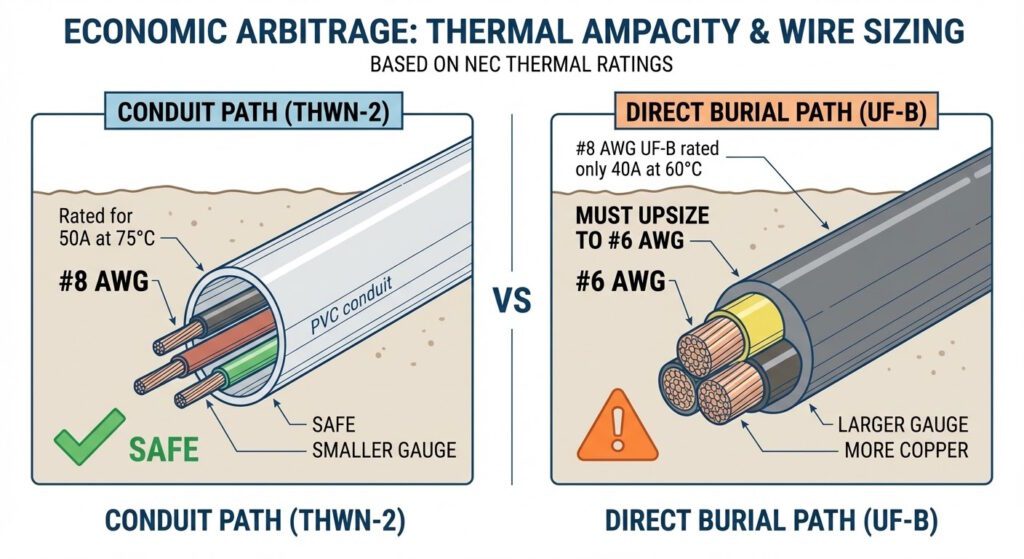
The Economic Arbitrage: Consider a 50 Amp subpanel load. A generic chart recommends #6 AWG. However, the Trench Digger identifies a thermal arbitrage opportunity:
- In a conduit path, #8 AWG THWN-2 is rated for 50A at 75°C. (Safe)
- In a direct burial path, #8 AWG UF-B is only rated for 40A at 60°C. It must be upsized to #6 AWG.
By surfacing this delta, the tool reveals that utilizing conduit often allows for a smaller wire gauge, saving upwards of 30% on copper mass—frequently offsetting the cost of the PVC entirely.
Why this matters in the real world
Most DIY trench mistakes happen because people price the run backwards. They start with cable cost, then try to justify the installation method. In reality, the installation method changes the thermal environment, and the thermal environment can change the conductor size you are allowed or forced to use.
That means a “cheaper” direct-burial path can become more expensive after upsizing, while a conduit path can sometimes preserve a smaller, more efficient wire choice. This is the kind of tradeoff that does not show up in casual calculator tools — but it absolutely shows up in the trench.
The Voltage Drop Recursion Loop
Once the thermal minimum is established, the calculator initiates a physics-based recursion loop to solve for Voltage Drop (VD). The engine enforces a strict maximum voltage drop threshold of 3% to protect sensitive electronics and motorized equipment.
The Mathematics of Sag
What the calculator is really checking behind the scenes
At its core, the calculator is not just measuring distance — it is testing whether your chosen wire size can carry current without excessive voltage loss over the full round-trip path.
Every change you make — wire gauge, trench length, or load — feeds into one question: does this run stay within acceptable voltage drop limits, or does it force a larger conductor?
The relationship below is what drives that decision:
The engine utilizes the standard Direct Current (DC) resistance formula adapted for single-phase Alternating Current (AC):$$VD = \frac{2 \cdot K \cdot L \cdot I}{CM}$$
Where the Variables Equal:
- $K$ (Constant): $12.9$. This is the specific resistance of Copper per mil-foot at operational temperatures (NEC Chapter 9, Table 9).
- $L$ (Length): The one-way run distance in feet.
- $I$ (Current): The load in Amperes (Breaker Size).
- $CM$ (Circular Mils): The cross-sectional area of the specific wire gauge (queried from our internal database of NEC Chapter 9, Table 8).
The While Loop Protocol
- Initialize: The engine takes the thermally sufficient wire size (e.g., 12 AWG / 6,530 CM).
- Compute: It calculates the exact voltage drop over the requested distance.
- Validate: It divides $VD$ by the base voltage (120V or 240V). If the result is $\leq 3\%$, the loop terminates.
- Iterate: If the drop $> 3\%$, the engine discards the current gauge, steps up to the next largest standard size (e.g., 10 AWG / 10,380 CM), and recalculates. A safety integer limits this to 10 iterations, preventing infinite loops.
Operational Impact: A 120V circuit running 150 feet on 12 AWG wire will experience a ~7.1% drop, delivering only 111V under full load. This causes compressor motors to overheat and digital systems to reboot. The Trench Digger engine mathematically forces the upsize to 8 AWG, resulting in a safe 2.8% drop.
In simple terms: longer runs, higher current, and smaller wire sizes all increase voltage drop — which is why underground installations often require upsizing sooner than expected.
Conduit Fill Geometry & The “Jam Ratio”
In “Manual Mode”, the application acts as a Conduit Fill Checker, utilizing a visual geometry engine to enforce NEC Chapter 9, Table 1.
Novice installers frequently assume a pipe can be filled to 100% capacity. The NEC legally restricts this to manage friction heat and pulling tension. The tool calculates the cumulative area of all conductors against the internal area of the selected PVC or EMT schedule.
The Three Zones of Fill Constraints
- 1 Wire: Maximum 53% fill.
- 2 Wires: Maximum 31% fill.
- 3+ Wires: Maximum 40% fill.
The 2-Wire Jam Ratio
Why is the legal limit significantly lower for two wires (31%) than for three wires (40%)? This is a critical engineering concept known as the Jam Ratio.
When two wires of roughly equal diameter are pulled through a raceway, they can twist and align side-by-side. If the sum of their diameters closely matches the internal diameter of the conduit, they act as a physical wedge on the bends, creating an unbreakable “jam” against the sidewalls. Three wires, by contrast, naturally form a triangular bundle that distributes radial pressure evenly, allowing for a higher 40% fill.
Validation in the App: If a user inputs two 6 AWG THHN wires into a 1/2″ EMT conduit, the total mathematical area equals 33.3% fill. A generic calculator applying the standard 40% rule would flag this as “Safe.” The Trench Digger correctly identifies $n=2$, switches the constant to 31%, and accurately triggers a Violation.
Equipment Grounding Conductor (EGC) Optimization
The Bill of Materials (BOM) generated by the app separates the phase conductors from the grounding conductor. This relies on NEC Table 250.122.
The Fallacy: DIYers often size their ground wire the same as their current-carrying phase conductors. The Optimization: Ground wires carry fault current only for fractions of a second, not the continuous operational load.
If a user requires a 100 Amp subpanel, the phase and neutral conductors must be sized at 3 AWG Copper. However, NEC 250.122 permits the Equipment Grounding Conductor to be as small as 8 AWG Copper.
Our algorithm isolates the ground, dynamically sizes it based on breaker amperage, and feeds the smaller diameter back into the Conduit Fill engine. This reduction in total bundle area frequently allows the entire system to fit into a smaller trade-size conduit (e.g., 1-inch instead of 1.25-inch), cascading into substantial cost savings on pipe and fittings.
Trench Depth Matrix (NEC 300.5)
Excavation labor is the highest variable cost—and the most physically demanding aspect—of any underground electrical project. The Trench Digger parses the user’s terrain input against NEC Table 300.5 (Minimum Cover Requirements).
- Standard Yard (Direct Burial): Column 1 dictates 24 inches of cover from the top of the cable to grade.
- Standard Yard (PVC Conduit): Column 3 reduces the requirement to 18 inches, owing to the physical protection of the raceway.
- Driveway Exception: If the logic detects a “Residential Driveway,” it applies an exception that reduces the Direct Burial requirement to 18 inches, matching conduit.
- Concrete Slab Exception: If routed under a minimum four-inch exterior concrete slab, the PVC depth requirement drops to four inches.
The application visually graphs these depth deltas. By showing the user that buying inexpensive PVC pipe can spare them the need to dig an extra six inches of compacted clay across a 100-foot trench, the tool provides immediate, actionable relief.
Underground Wiring: Key Questions Answered
Not always — but often. Direct burial cables (like UF-B) dissipate heat differently than conductors inside conduit. In some cases, that thermal environment can force upsizing to stay within safe ampacity limits, especially over longer runs.
Voltage drop increases with distance and current. Underground runs tend to be longer and harder to adjust after installation, so even small inefficiencies can compound. Excessive voltage drop leads to poor equipment performance and potential overheating.
Not always. Conduit adds material and labor cost, but it can improve thermal behavior and allow the use of smaller conductors. The “better” option depends on total system cost, not just trench simplicity.
Pricing the project based on cable cost alone. Burial method, voltage drop, and thermal limits can all change the required wire size — and that is where costs quietly increase.
Most basic calculators only account for distance and load. They often ignore trench depth, conduit fill, and thermal constraints. That’s why real-world results can differ from simple estimates.
When runs are long, loads may increase in the future, or voltage stability is critical (like for compressors or sensitive electronics). Oversizing reduces losses and provides headroom for expansion.
Conclusion & Tactical Deployment
The Trench Digger represents a shift from static tables to reactive, code-compliant simulation.
By layering thermal derating limits, voltage drop physics, geometrical conduit dynamics, and depth regulations into a single processing loop, the application delivers a result that guarantees three operational pillars:
- Legal Compliance: Strictly bound to NEC 2023.
- Asset Safety: Immunized against voltage sag and thermal overload.
- Economic Efficiency: Mathematically optimized for the smallest legal wire and raceway sizing.
For the modern homesteader, prepper, or DIY engineer, this eliminates the “guesswork tax”—ensuring your infrastructure is resilient, safe, and mission-ready from the moment you throw the breaker.
Don’t guess on underground wire sizing
If your trench plan looks “close enough,” that is exactly when mistakes get expensive. Check the run with the calculator, compare burial methods, and see whether wire size, depth, or conduit geometry quietly changes the answer.
Jump Back to the CalculatorThe Trench Digger: NEC Underground Wire Calculator (2023)

Discover the math behind our engineer-grade NEC underground wire calculator. We solve for voltage drop, thermal ampacity, conduit fill, and trench depth.
Price: 0.00
Operating System: web
Application Category: UtilitiesApplication