
Project: The Engineering Logic Behind the Transfer Switch Circuit Builder
Objective: To document the algorithms, electrical physics, and NEC standards powering the app for safe backup power planning.
Date: March 26, 2026
What this builder actually solves
Most homeowners do not fail backup-power planning because they forgot to buy a generator. They fail because they assume that if the generator wattage looks big enough, the transfer-switch plan must be safe. That is not how real systems fail.
This builder checks the things that actually cause trouble in the field: overloaded legs, startup surge collisions, voltage drop on long runs, undersized conductors, and neutral-bonding mistakes that can turn a “working” setup into a dangerous one.
Run this example first
Before you build your own setup, try a common emergency-load package like this:
If the builder recommends moving one motor load to the opposite leg, increasing wire size, or stepping up generator headroom, that is the exact kind of hidden failure this tool is designed to expose.
How to read your results
- Balanced Load: Both legs are carrying similar load — optimal generator efficiency.
- Overloaded Leg: One side is carrying too much — redistribute circuits.
- Voltage Drop Warning: Wire size or run length is reducing system performance.
- Surge Risk: Startup loads may trip the generator even if steady watts look safe.
This tool is not just estimating — it is identifying failure points before they happen.
Transfer Switch Circuit Builder: Start Here
Executive Abstract: The “Back-of-the-Napkin” Hazard
In the residential backup power space, planning is often dangerously simplified. When preparing for grid instability, homeowners typically perform what we call “napkin math.” They list their critical appliances—a refrigerator (700W), a furnace blower (600W), and a few lighting circuits (200W)—sum them to 1500W, and blindly purchase a generator and manual transfer switch that meet that raw total.
While arithmetically correct on paper, this approach fails spectacularly in an electrical reality. It ignores the dynamic, shifting physics of alternating current (AC) distribution. Napkin math fails to account for stator imbalance, inrush currents (surge), thermal voltage drop over distance, and the critical safety distinction between bonded and floating neutrals. When a blizzard hits and the grid goes down, discovering your phase imbalance is tripping breakers is not a tactical option.
To close this dangerous gap between “simple math” and “electrical reality,” we developed the HomePowerLab Transfer Switch Circuit Builder. This is not merely a shopping list generator; it is a browser-based physics engine that creates a functional “Digital Twin” of your emergency electrical project. This lab report details the engineering logic, mathematical formulas, and NEC (National Electrical Code) compliance standards hard-coded into the tool.
Physics Engine (How the Builder Calculates Load & Safety)
The core of the Transfer Switch Circuit Builder drives five distinct simulations simultaneously as you interact with the interface. Unlike static spreadsheets, the Builder treats every circuit as a dynamic variable in a larger, interconnected equation.
Load Balancing (Preventing One Leg Overload)
Most portable generators capable of powering a home supply 240V split-phase power, delivered via two 120V “hot” legs (often labeled Leg A and Leg B, or L1 and L2). The generator’s alternator (stator) is physically wound such that exactly half of its capacity rests on Leg A, and the other half on Leg B. Therefore, a 5000W generator is, for all practical purposes, two separate 2500W power sources sharing a single neutral return.
The Engineering Problem: If a user unknowingly stacks all their heavy, motor-driven 120V loads (Fridge, Sump Pump, Furnace) onto Leg A, they can severely overload half the generator while Leg B remains idle at 0W. When you load 3000W on Leg A and 0W on Leg B, the magnetic field inside the alternator becomes highly asymmetrical. This creates harsh mechanical vibration, excess heat, voltage sag on the loaded leg (dropping to 100V or lower), and dangerous voltage swell on the unloaded leg (spiking up to 140V). This scenario will catastrophically fry sensitive electronics like furnace control boards and television capacitors.
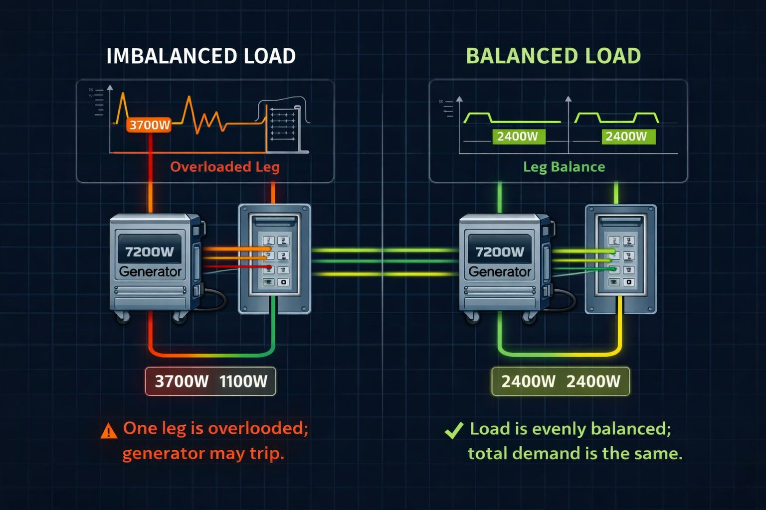
Even when total wattage looks safe, an uneven load across both legs can overload one side of the system. Balanced distribution is what keeps the generator stable under real conditions.
The failure modes this builder is trying to stop
- False confidence from nameplate watts: the generator looks large enough on paper, but startup loads trip it in real life.
- Leg imbalance: one side of the transfer switch carries too much load while the opposite side stays lightly loaded.
- Voltage drop: long conductor runs and undersized wire create performance loss and excess heat.
- Neutral-bonding errors: a misconfigured system may appear to work while violating safe generator-transfer-switch practice.
- Overlooked budgeting: the electrical plan “works” conceptually, but the wire, breaker, and switch costs were never modeled up front.
What the builder is checking behind the scenes
Load balancing across both legs
Voltage drop on conductor runs
Motor startup surge and LRA overlap
Neutral bonding and transfer-switch logic
The Lab Solution (The Math): The Transfer Switch Circuit Builder utilizes an active load-balancing algorithm. As you drag and drop 120V circuits into your virtual panel, the logic automatically alternates their phase assignment (A, B, A, B). The system constantly calculates the real-time phase disparity using the following equation:$$\Delta_{phase} = \frac{|P_A – P_B|}{P_A + P_B} \times 100$$
Where $P_A$ is the total wattage on Leg A, and $P_B$ is the total wattage on Leg B.
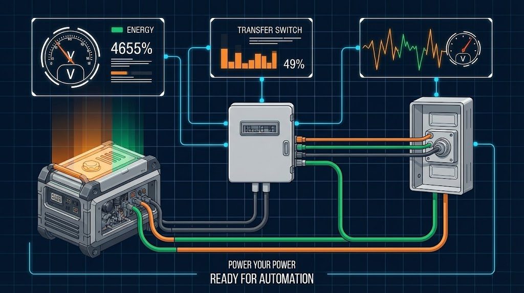
- Visual Feedback: Two analog-style VU meters display the load in watts on each leg in real time, simulating physical telemetry gauges.
- Active Monitoring: If the calculation yields $\Delta_{phase} > 10\%$, a red warning banner deploys, actively advising the user to “Swap Phases.”
- Manual Control: Users can toggle individual circuits between Leg A and Leg B to mathematically minimize $\Delta_{phase}$, virtually mimicking the physical act of moving a breaker in a box.
The Neutral Bond Safety Check (NEC 250.30)
The most frequent—and dangerous—code violation in DIY generator connections is the creation of a “Double Bond” or ground loop.
- Scenario A: Your home’s Main Service Panel has the Neutral bonded (connected) to the Ground bus (this is correct and required by code).
- Scenario B: Your Portable Generator also has its Neutral bonded to its metal Frame (highly common for OSHA job-site compliance).
Connecting these two bonded systems via a standard 2-pole transfer switch creates a parallel, uncontrolled path for neutral current to return to the generator source via the bare copper ground wire. This “objectionable current” electrifies the generator frame, instantly trips any GFCI receptacles on the generator, and creates a lethal shock hazard.
The Lab Solution: The tool forces a mandatory “Bonding Calibration” step before you build your panel.
- If you select “Bonded Neutral,” the recommendation engine overrides standard hardware and specifically mandates a 3-Pole (Switched Neutral) Transfer Switch. This hardware physically breaks the utility neutral connection before making the generator neutral connection, effectively treating the portable generator as a Separately Derived System and eliminating the ground loop entirely.
- If you select “Floating Neutral,” the Builder recommends the standard, more affordable 2-Pole Switch, which maintains electrical safety by using the main panel’s existing earth bond.
Transfer switches that match this system logic
Not all transfer switches are built the same. The correct choice depends on your generator’s neutral configuration and how your circuits are distributed.
Reliance Controls 31410CRK – 10-circuit manual transfer switch with watt meters for load balancing.
View on Amazon →
Use a 3-pole (switched neutral) transfer switch to avoid parallel neutral paths and potential hazards.
View Compatible 3-Pole Options →
Thermodynamics: Voltage Drop & Wire Gauge Calculation
Electrical resistance creates heat, and heat equals a loss of voltage. A 30-amp generator pushing current through 100 feet of standard 10-gauge wire will experience significant resistance. According to NEC Chapter 9, Table 8 (Conductor Properties), this physical resistance inevitably results in a voltage drop at the load end of the run.
The Lab Solution (The Math): The Transfer Switch Circuit Builder features a WireLength slider that acts as a real-time variable ($L$) in a standard single-phase AC voltage drop calculation:$$V_{drop} = \frac{2 \times L \times R \times I}{1000}$$
Where:
- $L$ = One-way length of the cable in feet.
- $R$ = Conductor resistance per 1000 ft ($1.2\ \Omega$ for 10AWG, $0.78\ \Omega$ for 8AWG copper).
- $I$ = Load current (calculated at a maximum of 30A for an L14-30 connection).
The percentage drop is then evaluated: $\text{Drop \%} = (V_{drop} / 240) \times 100$.
- < 75 Feet: The app mathematically validates that standard 10/3 NM-B wire keeps the voltage drop safely below the NEC-recommended 3% threshold.
- > 75 Feet: The logic engine detects that the voltage drop will exceed 3%. Low voltage causes motors to draw more amperage to compensate, overheating their windings. To prevent this, the app triggers a critical alert and dynamically updates the Bill of Materials (BOM) to recommend thicker, lower-resistance 8/3 NM-B wire.
The NEC 125% Rule (Thermal Continuous Loads)
Not all wattage is created equal. Code requires that for electrical loads operating continuously for three hours or more (e.g., area lighting, electric resistance space heating), the circuit protection and conductors be rated at 125% of the actual load. Why? Because a 1000W heater drawing current for hours generates ambient heat inside the breaker box, it slowly shifts the circuit breaker’s thermal trip curve.
The Lab Solution (The Math): A “Continuous Load” toggle is available for every circuit. Activating it alters the underlying capacity algorithm:$$P_{capacity} = \begin{cases} P_{load} & \text{if non-continuous} \\ P_{load} \times 1.25 & \text{if continuous} \end{cases}$$
This ensures your panel sizing adheres strictly to NEC 210.19(A)(1), preventing nuisance tripping during prolonged outages, while intelligently keeping the fuel consumption estimate accurate based purely on the un-multiplied watt-draw.
If your wire run exceeds ~75–100 feet under load, voltage drop becomes significant. The builder compensates for this by recommending thicker conductors to prevent heat loss and performance issues.
Inrush Current (Surge / LRA) Dynamics
Electric motors require a massive, momentary spike of energy to break physical inertia—a phenomenon known as Locked Rotor Amps (LRA). A refrigerator that runs at 700W might require 2200W for a fraction of a second to start the compressor.
The Lab Solution: The Transfer Switch Circuit Builder independently tracks both Running Watts and Starting Watts. It automatically calculates your maximum potential surge load ($P_{surge\_max} = \sum P_{running} + \max(P_{surge\_delta})$), ensuring that the generator recommended in the final report has an alternator robust enough to handle the inrush current of your largest motors without stalling the engine.
The Logistics & Output Engine
Beyond electrical physics, deploying a backup power system requires meticulous logistical and financial planning. The tool translates your digital twin into actionable deployment protocols.
Live Fuel Consumption Estimator
Based on the total sum of running watts, the Builder provides a live projection of your fuel consumption. To provide a realistic figure without knowing the exact model of your engine, the lab relies on a thermodynamic heuristic for standard splash-lubricated OHV portable generator engines:$$\text{Fuel Rate (GPH)} \approx \left( \frac{\sum P_{running}}{10000} \times 0.8 \right) + 0.2$$
This formula establishes a baseline idle consumption ($0.2$ Gallons Per Hour) and scales fuel burn linearly with the electrical load, giving the user a highly accurate basis for planning their fuel storage logistics.
Total Project Cost Estimator
Pricing out a project based solely on the transfer switch box is a recipe for a blown budget. The builder synthesizes a comprehensive estimate:
- Core Hardware: Switch Kit + L14-30 Power Inlet Box + Generator Cord.
- Variable Copper Costs: Calculates the estimated cost of the interior NM-B wire based on the exact footage ($L$) and the specific gauge required (10AWG vs 8AWG) derived from the voltage drop formula.
- Infrastructure: Adds baseline estimates for necessary conduit kits and electrical sundries.
Dynamic Vector Schematics (The “Blueprints”)
The application generates an exportable, 3-page PDF that serves as your installation blueprint. It renders a Technical Wiring Schematic on the fly using precision vector graphics.
- Pinout Accuracy: It draws the NEMA L14-30P plug face, explicitly identifying the Hot (X/Y), Neutral (W), and Ground (G) pins for visual confirmation.
- Circuit Interception Detail: A dedicated inset diagram illustrates the physical workflow: how to detach an existing house wire from the main breaker, wire-nut it to the transfer switch’s load wire, and land the switch’s line wire back onto the main breaker.
- Context-Aware Architecture: The system schematic intelligently adapts based on your previous Bonding Check. If you selected a Bonded Generator, the diagram explicitly illustrates the Neutral wire passing through the transfer switch toggle mechanism. If floating, it shows a solid, un-switched connection to the neutral bus bar.
State Serialization (Save & Share Your Wiring Plan)
To facilitate seamless collaboration between homeowners and licensed electricians, the app utilizes Base64 state serialization. The entire complex state of your project—every selected appliance, breaker size, wire length, and generator type—is cryptographically encoded into a unique hash string in your browser’s URL.
- Tactical Utility: A homeowner can meticulously design their system, click “Share,” and text the resulting link directly to their electrician. The electrician opens the link and sees the exact same loadout, load meters, and NEC warnings, allowing for instant professional verification without any redundant data entry.
Transfer switch builder FAQ
Is generator wattage alone enough to size a transfer switch plan?
Why can a setup fail even if the running watts look fine?
Why does leg balancing matter in a transfer switch?
What is this tool best for?
Conclusion: Tactical Autonomy
The HomePowerLab Transfer Switch Circuit Builder represents a necessary shift from “guessing” to “engineering.” By actively enforcing the laws of physics, thermodynamics, and the National Electrical Code during the planning phase, we drastically reduce the risk of equipment damage, electrical fire, and budget overruns. It transforms a highly complex electrical engineering challenge into an intuitive, visual experience—ensuring that when the centralized grid fails, your localized power plan holds up safely and flawlessly.
Transfer Switch Circuit Builder: Load Balancing & Wiring Schematics
Stop guessing with napkin math. Our "Lab-Level" Transfer Switch Circuit Builder simulates your home's backup power physics—calculating phase balance, voltage drop, and neutral bonding—before generating a custom wiring schematic and budget.
Price: 0.00
Operating System: web
Application Category: UtilitiesApplication